Hello and welcome! I’m Mike and I’ll be your writer for this evening (or morning or whatever) … I’ll be your writer for this moment of time that properly represents the moment of time during which you are reading this article. Today’s special is “My Favorite Project.” It comes with a side of humor and some pictures!
First, this isn’t intended to be a tutorial, but rather an overview of my process and the tools used to get to the end product. Also, I suppose this isn’t technically my favorite project, but that is only because I like many of my projects involving problem solving and learning new things. I guess THAT is my favorite!
You may have noticed that the tone and style of this article is somewhat different than other articles on our site. That is partially because I don’t write the other articles and partially because this could be really boring for both of us and that is just not as much fun as this!
Ok! Let’s get started! 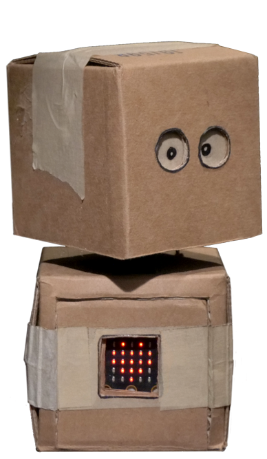
Many of you may be familiar with our little buddy Elby. He is one of the adorable stars of the CodeJoy student show. What you may not know about Elby is that there is only one of him. This is not a great thing when you are working in a garage in the midwest/appalachia and said little buddy is 90% cardboard and painters tape. Tragedy could strike at any time!
Why only one I hear you ask? Go on! Ask it!
Well, it turns out that recreating this little fellow is somewhat challenging because of how gosh darned cute he is and because he was handmade. As a result, attempts to recreate Elby have not so much resulted in failure as in the creation of other characters in the CodeJoy universe. So…time marches on and Elby gets stored as carefully as possible and he remains unique.
If everything is fine then why is a new Elby needed? Did Elby go soggy on us? In short…no, but he might. You see, we partnered with NASA TechRise Challenge to design and perform a new student show for some super amazing young inventors. The main plot of this show (spoiler alert) is that Elby, through various shenanigans, ends up on a high-altitude balloon. Of course this was not a real balloon with real sky and real clouds, but just a set in our studio. So don’t worry, Elby was not in danger! …yet…
After the shows were over we were contacted about sending Elby up on a REAL high-altitude balloon. You can see the danger…balloons, high up, with clouds. Plus they really didn’t want all the servos and such due, I suspect, to the unnecessary weight. So all that together means that Elby needs a stunt double! Plus as a side benefit I needed to figure out a way to make additional Elby units and maybe some upgrades because at heart I’m really an inventor and tinkerer. I’m also a fan of 3D printing and just got a couple of be printers from Bambu Lab that I absolutely LOVE. This will be important later on…
After a little thinking and research I decided the best way to faithfully recreate Elby was to use the tried and true method so often used by people in movies who are working in an office with a copier for the first time. I asked Matt to slap Elby face first on a scanner and send the resulting image to me. Oh yea…and also could you put a ruler on there with him because otherwise it would be just plain weird. And just like that I had this:

Great! I have a weird scan of Elby and a ruler, now what? My thought was to somehow use this image to create a 3D printed template for the important design elements of Elby. Why not use cardboard? Well, if I used cardboard we would have the same problem at some point in the future and the template would again be hard to reproduce. With 3D printing I can design the template and as long as I still have the design files I can easily recreate it by printing it again. Also, 3D printing is cool! So, the plan is to create templates for important characteristics like his head/eye placement, neck servo and the little door for the micro:bit.
Enter the first challenge! Up until this point I have used Tinkercad when I needed to build a custom 3D model. Don’t get me wrong, I have made many interesting and useful things using Tinkercad, but it just didn’t seem like the right tool for this kind of work. I knew design iteration was going to be important and small adjustments in TInkercad are tedious. I also felt like it was time to up my 3D design game. Let the search for alternate software begin!
I started my search like any normal person and consulted the experts. By this I mean I started watching video reviews and tutorials on YouTube. To cut a long story short I tested out a number of options both free and paid and ended up selecting Shapr3D because it had a relatively inexpensive subscription that allowed commercial use and it is a history enabled, parametric modeling program. There are plenty of other low cost or free options out there for markers, hobbyists, and educators, but the free options were a little too rough for me and the paid options get really spendy if you want the ability to use the results for commercial purposes. I am always looking for the monetary cliff point when it comes to software, so that was important to me.
Now that the software was selected, I imported the image of Elby and started sketching in Shapr3D. First, I drew a line 10mm long and scaled up the drawing until 10mm on the ruler matched the 10mm line. Then I could trace the box head and properly position the eyes. Incidentally, it turned out that his eyes are not exactly level which makes him even cuter. Anyhow, once I had a good sketch I extruded the body and added some positioning fins on the sides and a label so I knew which way was the top of his head. I then exported the model and sent it to be printed on my trusty P1S. Here is the result:


After a test fit on a 3” box I did the same thing for Elby’s body.
I now have a tool that lets us easily position the eyes and body openings. These are used as drawing guides and not cutting guides. I have found that imprecise cutting is part of Elby’s charm, so you don’t want to be too perfect!


The path diverges here depending on if you are making a functional Elby or a static (aka stunt) Elby:
Functional Elby:
For a functional Elby I need to be able to attach 2 servos together to form a mechanism that allows Elby’s head to pitch (vertical movement) and yaw (horizontal movement). In the past we just hot glued a servo horn on one servo to the side of another servo, then hot glued the second servo horn to a spacer like wood or cardboard, then to the inside of the side of Elby’s head.

This works great until it doesn't. For example you have to choose if you are going to screw the servo horns to the servos before you glue. If you do then you have a problem if one or both of the servos goes bad on you. How are you going to replace them? If you don’t attach them then you have good fixability, but it increases the odds that Elby’s head will fall off. Also not great!
Finally, there is no 3D modeling or printing involved in those options and what fun is that!? So I modeled a connector that let you attach two servos together in the proper orientation with this part, a servo horn and some screws. I now have a repairable and secure dual axis servo assembly. Why did I use a servo hon instead of attaching the 3D printed bracket directly to the servo? It comes down to strength. Though this decision makes the connector a little more complicated, the strength of the injection molded servo horn that is specifically designed to work with the servo is greater than I could achieve with a 3D printed part alone. By using both parts I get strength and customization and all it cost me was an extra sketch and some quality time with my calipers.


Great! I have a 3D printable bracket to make the pitch/yaw mechanism with 2 servos that is fully repairable! Hazza! Of course it will only work if your servo horn fits in the depression, but as long as we use the same servos that shouldn’t be an issue. Worst case scenario I have to modify the design for a different servo horn shape. No biggie.
I also took this opportunity to upgrade Elby’s servos to metal gear servos to help with the longevity of the build. At the time the metal gear servos were significantly cheaper than the similar plastic gear variant for some reason, so win, win I guess! (If you are curious I am using MG996R servos.)

The next consideration for fixability is attaching the pitch servo to the inside of Elby’s head. As part of this design I wanted to make it easier to mount the head to the servo. After some tinkering I modeled a 2 part attachment mechanism where one part is attached to the head the other part is attached to the servo (again with the servo horn inset). I played around with this design and made some small prototypes before starting on full size prints. The main thing I needed to test were the tolerances to allow the two pieces to slide together without a lot of wiggle afterward and a clip at the bottom that is used to hold the part together, but still able to be released. A few tests later and I had a pretty good solution!

Now that I had all the parts I needed I was able to hot glue the sleeve inside Elby’s head, place the servo assembly on the body and slide the head in place. Then, using the clip I could easily remove the head if needed.

Great, right!? Well, almost. The metal gear servos are a little heavier than the plastic gear servos which made the cardboard a little wobbly when the head moved. The solution? 3D printing of course! I sketched up a brace to slide around the servo inside his body. One screw from the top and we have a nice and secure neck assembly!
Finally we cut the hole in the body for the yaw servo and a hole for the yaw servo wire and the mechanical construction of a functional Elby is complete!

Now for the stunt double…
Static (Stunt) Elby:
The stunt Elby is a little easier because he does not need to move, so no servos. However, part of Elby’s appearance is one of the servos you can see in his neck assembly. How will I ever solve this problem?
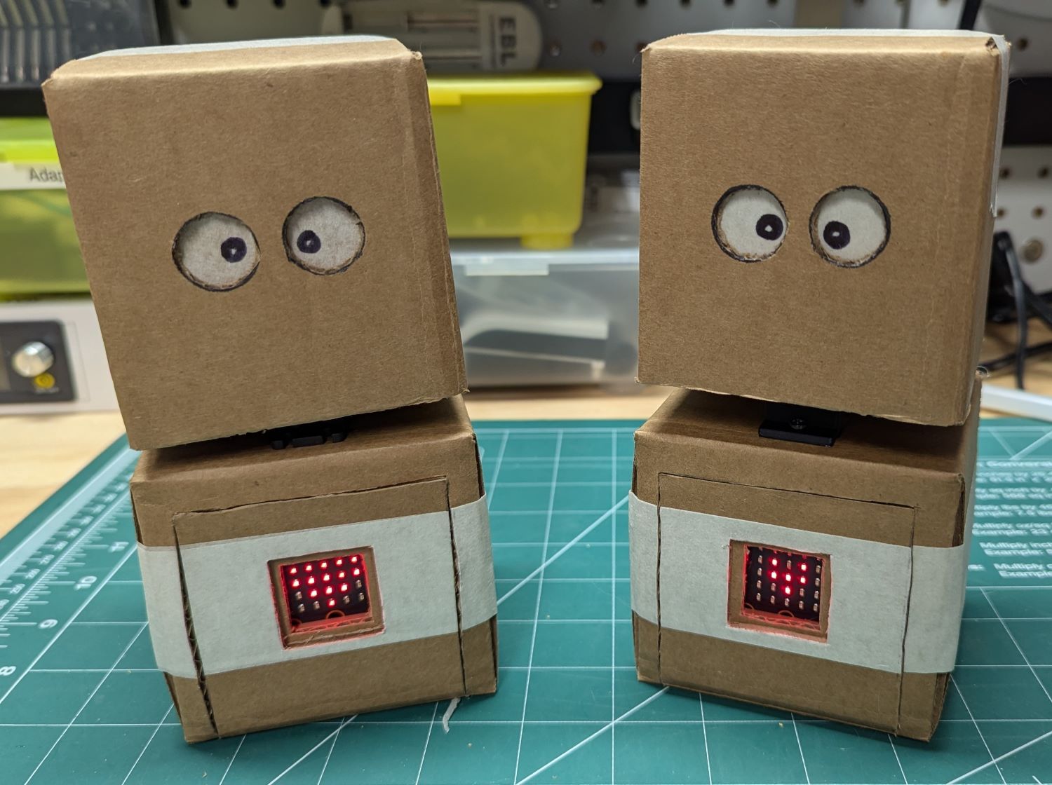
3D design and printing to the rescue! I mocked up a fake servo and another brace to hold the head to the body, then a bracket to attach to both sides of the inside of his head. From the front it still looks like a normal Elby with servo, but without all that pesky movement and the head bracket is secured to the mock servo with a M3 screw into a threaded insert that was heat inserted into the mock servo. Then secure the mock servo to the body with the interior brace and attach the head bracket to the head and you have a nice and secure non-functional Elby! The biggest difference is that stunt Elby is not as reparable. I sacrifice reparability for solid construction.


Finishing Up!
Now that we have the two options for neck assemblies designed we can finish up our Elby. We need to install the micro:bit with the beating heart program. This involves cutting a second piece of cardboard as a spacer that has a square slightly smaller than the square in his body. You also need to cut gaps in the square for the buttons of the micro:bit. Did I make a template for this as well? Of course I did!

We then secure the micro:bit with tape and we have a completed Elby assembly!
Wait! Hold the presses! As I was attempting to tape the micro:bit in place I realized this was crazy. Every time I want to remove the micro:bit I have to mess with a bit of tape? What am I? An animal! Well… yes, but I’ve got thumbs…and a 3D printer! So I sketched up a little sleeve for the micro:bit to fit in and used that instead!


Oh wait…you want to know how we control the functional Elby? In the current model we use in shows (the original Elby) a Hummingbird Robotics kit and micro:bit are used. However, any board capable of controlling servos would work.
To illustrate that I wanted to see if I could get everything inside Elby’s body with just one USB C cable just to provide power. For the control interface I wrote a web based program in Python for a Raspberry Pi Zero 2 operating an I2C connected PCA9685 based servo controller board. Both of these are pretty inexpensive and readily available again. The current software allows for single servo movement, multi servo movement and programmable motions, but it is still a work in progress.

If you look carefully you will notice a battery in there. In this prototype Elby can be USB powered it is also capable of being fully wireless! I am having a little power issue where the controller board loses power sometimes while on battery, but this is a prototype.
If you made it this far I want to say thank you for hanging in there. I hope you found this article interesting if not helpful.
If you are interested in more about the internals of Elby let us know and maybe I’ll put together another article with more details. :)
Happy building!
-Mike